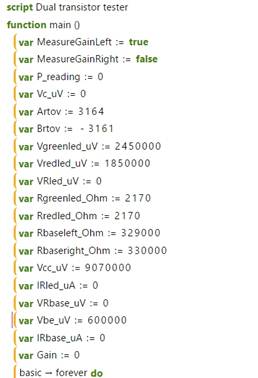
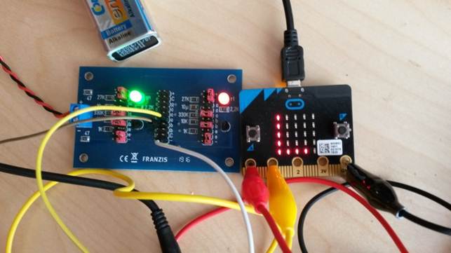
 Dual transistor tester with the BBC micro:bitDual transistor tester with the BBC micro:bit
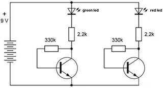
By measuring the Vc's of each transistor,
their gains -- being the ratios of the collector and bias currents ic and ib
respectively, and assuming constant voltages with values Vbe = 0.6 V, Vgreenled
= 2,45 V and Vredled = 1,85 V -- can be calculated.
In formulas: gain = ic / ib
ib = (Vc - Vbe)
/ Rb
ic = (Vcc -
Vled - Vc) / Rc
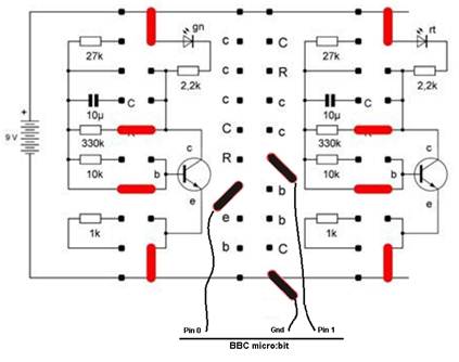
Calibration of the ADC of the micro:bit
The micro:bit's ADC was calibrated using the stable voltage of a Li-cell and a zero voltage, the Li-cell supplying 2.93 V.
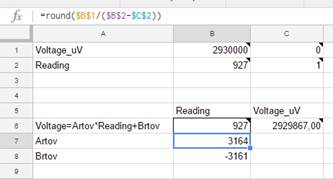
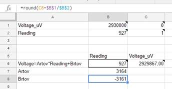
Since the micro:bit deals with intergers only, voltages were expressed in microvolts, currents in microamps and resistances in ohms.
A linear relationship was used: Voltage in microvolts = 3164 * ADC_reading - 3161.
Results
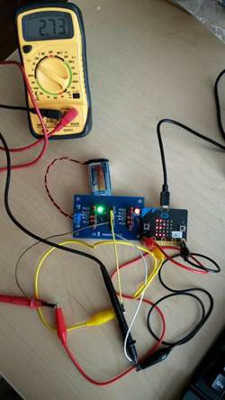
https://goo.gl/photos/gdCqADEAYpKVN5Aa7